Friday, December 31, 2010

Watermain Coverage Solu-Around

This solu-around provides a very efficient solution for checking the minimum coverage along the entire length of watermain . This could also provide an easy way to design watermain if utilized correctly.
The overall goal is simple. Copy the existing ground profile to a minimum depth.  
A few simple steps are provided.
1.Create a profile over alignment (pipe run). 2. Select existing ground surface in profile view and use the AutoCAD copy command to duplicate it. 3. Select new existing ground profile, select profile propertie and name it Watermain minimum coverage and set a unique profile style.
4. Select new profile, right click and select profile properties. Navigate to the Profile Data tab, and move the scroll bar until update is located. Change the watermain coverage profile to static.


5.Select the profile and notice all of the grips that are highlighted. The profile is no longer dynamic to the surface. Now we are able to move the profile down to check for minimum coverage.
6.With the profile selected pick geometry editor. Locate the raise lower PVI icon and select it. Set this to the depth required for minimum coverage. Make sure you specify a negative number.


 Two profiles should be showing.

Adjust the pipe to make sure it is below the new surface.


This concludes a simple watermain solu-around.

Saturday, December 11, 2010

Corridor Driveways, Sidewalks and ADA Ramps - Autodesk University 2010 ONLINE

Autodesk University was great. Had a lot of fun in VEGAS, it’s like a play ground for grownups. If you were unable to make the conference this year check it out online. All classes are available for FREE if your company is on subscription. Autodesk University Website

Please check out my class this year and classes I did previously.

Endless Corridors with AutoCAD® Civil 3D_ CV422-2 -2010
Diversify Visually with Autodesk Civil 3D_DV322-1 - 2009
Don't be left out in the CODE_CV9314-1 - 2009

ENDLESS CORIDORRS
The most prolific topic that I discussed was utilizing Conditional Subassemblies, ConditionalHorizontalTargets to complete driveways, sidewalks and ADA ramps. Below is an example of how this works.


Plan view results applying one assembly. Notice the curb is removed from the drive ways, and the sidewalk continues through the walk, but is removed from the road. This is accomplished by simply placing polylines at critical locations. The conditional subassemblies have an option to look for the nearest or the farthest target and associating the correct subassembly. The red polylines placed on the driveway applies the gutter subassembly and the green polyline marks the target for where a region should be placed so no subassembly is applied. More elaborate subassemblies can be developed to utilize conditional subassemblies after each individual subassembly. Have fun and remember to place and test the targets are working, before applying the no target subassembly.
Review the class for further details on this concept and unique way to handle intersections

Wednesday, December 8, 2010

Compose subassemblies visually for FREE

Check out the latest in Autodesk Labs and the best part, the software is FREE. This tool was deleloped to modify or build custom subassemblies without .NET knowledge.

Features

The technology preview release provides a strong set of subassembly functionality for corridor modeling:
■ Define points and position them based on several positioning methods.

■ Define links between points.

■ Assign codes.

■ Define targets and input parameters.

■ Specify conditions for daylight and simple expressions.


Video link is provided for quick overview; http://www.youtube.com/watch?v=VnNO9vzxp6A

Login to Autodesk Labs; http://labs.autodesk.com/

Link to subassebly creater; http://labs.autodesk.com/utilities/civil3d_subassembly_editor/

Wednesday, November 10, 2010

CIVIL 3D POINT SYMBOL ROTATION ONLY

This solu-around rotates point styles (symbols) without rotating point label styles (text). Notice below the default behavior. Select the circular grip and the symbol and text is rotated.


At this time Civil 3D 2011 the effective solu-around is to change the point label style behavior setting for orientation reference from object to view. If the reference is set to object the text rotates with the object, but if this is changed to view the text is oriented with the view. See image below to set the point label style to view.


Now as the symbol/point is rotated the text remains oriented to the view.


To obtain desired results, create a new label style for symbols that may require rotation or create a point group with a point style override and only include the points that are rotated.

An alternative solution is to create a dragstate and set the point label style to stacked text. With this method only one color can be selected for the text. Drag the point to the right, and rotate the symbol using the circular grip. The text remains in the dragstate without rotating the text. Below are the settings for the dragstate and expected results.


New point style for the symbols that require rotation. Set the rotation custom to the style.


Monday, October 25, 2010

Points Display Solution

To review points that are too close together simple change the drawing scale located in the bottom right. Points are automatically resized. See preview below where the scale was 50 and adjusted to 10.
Sometimes the simple approach is the ideal solution.

Monday, October 11, 2010

FLICKERING SCREEN after installing the Civil 3D 2011 update

A client brought this to my attention after installing the Civil 3D 2011 update on a 64 bit machine.

We found a fix online.  Type 3DConfig in the command line.  Click on Manual Tune.  Uncheck, then recheck “Enable Hardware Acceleration”.


Thanks for pointing this out Eric


Thursday, September 2, 2010

iPhone APP for AutoCAD

When I grew up there was no such thing as AutoCAD. I can't even  begin to imagine editing design documents on my phone. Coming this fall; AutoCAD will be available on the iPhone. Yes there is an App for that and it's free. Here is an example of a phone conversation with me at AU this year.

Hang on a minute, I just recieved a text, sorry about that, had to update a drawing for the client.
Detailed information about AutoCAD on a MAC and the iPhone App

Like I said, I will be reviewing drawings at AU.
Download the APP today at AutoCAD APP

Tuesday, August 31, 2010

Profile creation from a Feature Line

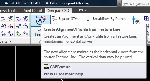
Select a feature line, right click and create a quick profile. A quick profile can be saved by exporting an xml file before saving the drawing. Importing the xml file will create an alignment. Use the create profile command to re-display the quick profile. Below are a few examples where this could be used.

Create a profile from a single row of points.
Draw a feature line using the transparent command point objects (‘PO). Connect the row of points. Select the feature line, right click and create a quick profile. Export and then import the xml file. Using the profile pulldown select create profile view.

Design a parking lot with feature lines - Daylighting
Design a parking lot with feature lines. Select the feature line, right click and create a quick profile. Export and then import the xml file. Create a profile view, now you can use an assembly to daylight the parking lot.
Drainage review – Parking Lot, Drains, ETC
This could also be used to analyze edge of pavement or curb lines for drainage. Create a quick profile from any feature line. Choose different styles to display existing ground and the feature line as the finished ground. Under the home tab locate Profile View, select the last option, Project Objects To Profile View. (This requires style to display labels and symbols.)

*NOTE: The profile is only temporary unless it is exported as xml and re-imported. (See steps above)


I pulled this Solu-Around from the bottom of my Civil 3D TIP JAR. If you have been utilizing this feature and understand its potential like I have, check out the upgraded version at Sincpac-C3D. http://www.quuxsoft.com/


It has been brought to my attention, that the alignment is not created after importing the XML in Civil 3D 2011. Like I said this tip was pulled from the tip jar. The Solu-Around (solution) is to click pick from drawing and select the profile to export. Now when you import the XML the alignment will be there.


Tuesday, August 17, 2010

Does the BIGGEST mean the BEST?

Two of the largest Autodesk resellers become one!

RAND WORLDWIDE, INC. AND AVATECH SOLUTIONS, INC.
This will form the larget Autodesk global VAR
http://www.rand.com/1/about/investor/news2010.htm

Wednesday, August 4, 2010

Essential grade label for Site Design

Arrows reflect grade; elevation and grades update as modified.


Styles are imperative to Civil 3D and I haven’t even mentioned my favorites in this blog yet. The first one I would like to introduce is an oldie, but it always slips under the radar. I’m sure by now everyone is familiar with direction arrows for line labels, but did you know that out of the box Civil 3D provides a direction label style for grades? Apply this to any feature line and it places an arrow pointing in the downhill direction. To try this open the NSC template and click on the Annotate tab, click add labels and select Grade only for the label styles.

The secret is an expression that was created to allow the direction arrow to rotate.

The default label style should look like this after placing labels on a feature line with elevations.
Detailed information from Autodesk


Now that we have found the default style let’s elaborate by adding elevations.Copy the current style and rename it ELEV & Grades. Add a text component.


Configure Anchor Point to the Start of each feature line, add the elevation to the start segment, rotate it 90 and set an offset.

The new style should include elevations. Make sure you repeat for curve labels.


Now it’s time to have some fun with this style by adding markers and moving the arrows to the lines.


Modify the design and watch the elevations, grades and slope arrows automatically update. Add Sincpac (3rd party software and link the points to the feature lines.)Please look for future post as we discuss this style, and other solu-arounds for site grading.

Shoot me an email and I will send the completed style to you. Should be posted on ADSK Solutions website soon.