When I grew up there was no such thing as AutoCAD. I can't even begin to imagine editing design documents on my phone. Coming this fall; AutoCAD will be available on the iPhone. Yes there is an App for that and it's free. Here is an example of a phone conversation with me at AU this year.
Hang on a minute, I just recieved a text, sorry about that, had to update a drawing for the client.
Detailed information about AutoCAD on a MAC and the iPhone App
Like I said, I will be reviewing drawings at AU.
Download the APP today at AutoCAD APP

Thursday, September 2, 2010

Tuesday, August 31, 2010
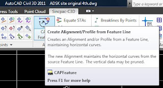
Profile creation from a Feature Line
Select a feature line, right click and create a quick profile. A quick profile can be saved by exporting an xml file before saving the drawing. Importing the xml file will create an alignment. Use the create profile command to re-display the quick profile. Below are a few examples where this could be used.
Create a profile from a single row of points.
Draw a feature line using the transparent command point objects (‘PO). Connect the row of points. Select the feature line, right click and create a quick profile. Export and then import the xml file. Using the profile pulldown select create profile view.
Design a parking lot with feature lines - Daylighting
Design a parking lot with feature lines. Select the feature line, right click and create a quick profile. Export and then import the xml file. Create a profile view, now you can use an assembly to daylight the parking lot.

*NOTE: The profile is only temporary unless it is exported as xml and re-imported. (See steps above)


I pulled this Solu-Around from the bottom of my Civil 3D TIP JAR. If you have been utilizing this feature and understand its potential like I have, check out the upgraded version at Sincpac-C3D. http://www.quuxsoft.com/

Create a profile from a single row of points.
Draw a feature line using the transparent command point objects (‘PO). Connect the row of points. Select the feature line, right click and create a quick profile. Export and then import the xml file. Using the profile pulldown select create profile view.
Design a parking lot with feature lines - Daylighting
Design a parking lot with feature lines. Select the feature line, right click and create a quick profile. Export and then import the xml file. Create a profile view, now you can use an assembly to daylight the parking lot.

Drainage review – Parking Lot, Drains, ETC
This could also be used to analyze edge of pavement or curb lines for drainage. Create a quick profile from any feature line. Choose different styles to display existing ground and the feature line as the finished ground. Under the home tab locate Profile View, select the last option, Project Objects To Profile View. (This requires style to display labels and symbols.)
*NOTE: The profile is only temporary unless it is exported as xml and re-imported. (See steps above)


I pulled this Solu-Around from the bottom of my Civil 3D TIP JAR. If you have been utilizing this feature and understand its potential like I have, check out the upgraded version at Sincpac-C3D. http://www.quuxsoft.com/
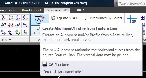
It has been brought to my attention, that the alignment is not created after importing the XML in Civil 3D 2011. Like I said this tip was pulled from the tip jar. The Solu-Around (solution) is to click pick from drawing and select the profile to export. Now when you import the XML the alignment will be there.

Tuesday, August 17, 2010
Does the BIGGEST mean the BEST?
Two of the largest Autodesk resellers become one!
RAND WORLDWIDE, INC. AND AVATECH SOLUTIONS, INC.
This will form the larget Autodesk global VAR
http://www.rand.com/1/about/investor/news2010.htm
RAND WORLDWIDE, INC. AND AVATECH SOLUTIONS, INC.
This will form the larget Autodesk global VAR
http://www.rand.com/1/about/investor/news2010.htm
Wednesday, August 4, 2010
Essential grade label for Site Design
Arrows reflect grade; elevation and grades update as modified.

Styles are imperative to Civil 3D and I haven’t even mentioned my favorites in this blog yet. The first one I would like to introduce is an oldie, but it always slips under the radar. I’m sure by now everyone is familiar with direction arrows for line labels, but did you know that out of the box Civil 3D provides a direction label style for grades? Apply this to any feature line and it places an arrow pointing in the downhill direction. To try this open the NSC template and click on the Annotate tab, click add labels and select Grade only for the label styles.

The secret is an expression that was created to allow the direction arrow to rotate.

The default label style should look like this after placing labels on a feature line with elevations.

Now that we have found the default style let’s elaborate by adding elevations.Copy the current style and rename it ELEV & Grades. Add a text component.

Configure Anchor Point to the Start of each feature line, add the elevation to the start segment, rotate it 90 and set an offset.

The new style should include elevations. Make sure you repeat for curve labels.

Now it’s time to have some fun with this style by adding markers and moving the arrows to the lines.

Modify the design and watch the elevations, grades and slope arrows automatically update. Add Sincpac (3rd party software and link the points to the feature lines.)Please look for future post as we discuss this style, and other solu-arounds for site grading.
Shoot me an email and I will send the completed style to you. Should be posted on ADSK Solutions website soon.
Monday, July 26, 2010
AutoCAD Civil 3D 2010 Update 3 available
Please read AutoCAD® Civil 3D® 2010 Update 3 Readme file before installing. This update resolves Ciivl 3D, Map 3D and AutoCAD issues.
Download update
Download update
Friday, July 2, 2010
Point Table with Station Offset Data
In Civil 3D 2011 it is not possible to create a dynamic point table with station and offset data. However it is possible with 3rd party software. http://www.quuxsoft.com/
If purchasing 3rd party is out of the question the tip below will provide a point table with station data that is not dynamic. This is possible by exporting an XML report to word and importing it to Civil 3D. Exporting to various formats provides efficient workflows for import back to Civil 3D.
Note: NET reports can be saved in several formats, including HTML, Adobe® PDF, Microsoft® Word Document, Microsoft® Excel Workbook, and Text Document. If Microsoft® Office is not installed, than the options for Word Document, Excel Workbook, and Text Document are not available
First let locate the toolbox icon.

Select the toolbox icon on the left to customize reports.
Locate the Toolbox tab and right click Station Offset to Points

Unfortunately this command will include every point in the drawing. If the point numbers are known you could select each one or remove the unwanted points. An easier workflow is erase points from the current drawing (to be safe do a save as before removing points). Erase the points that are not to be included. I wanted to include all points 100’ from the alignment so I offset the alignment 50’. Connected these lines to form a polyline and then offset the polyline another 50’.
Once the area is established the points were selected and erased. Below is what the drawing looked like before creating the report.


If purchasing 3rd party is out of the question the tip below will provide a point table with station data that is not dynamic. This is possible by exporting an XML report to word and importing it to Civil 3D. Exporting to various formats provides efficient workflows for import back to Civil 3D.
Note: NET reports can be saved in several formats, including HTML, Adobe® PDF, Microsoft® Word Document, Microsoft® Excel Workbook, and Text Document. If Microsoft® Office is not installed, than the options for Word Document, Excel Workbook, and Text Document are not available
First let locate the toolbox icon.

Select the toolbox icon on the left to customize reports.
Locate the Toolbox tab and right click Station Offset to Points

Unfortunately this command will include every point in the drawing. If the point numbers are known you could select each one or remove the unwanted points. An easier workflow is erase points from the current drawing (to be safe do a save as before removing points). Erase the points that are not to be included. I wanted to include all points 100’ from the alignment so I offset the alignment 50’. Connected these lines to form a polyline and then offset the polyline another 50’.
Once the area is established the points were selected and erased. Below is what the drawing looked like before creating the report.

The secret to creating the report is exporting it word format.

This is the report created in word. Notice it is customized to ADSK Solutions. This was accomplished with the red toolbox icon earlier.

Simply select report, copy it and select paste special in Civil 3D.

Once the table is in Civil 3D select the report and change the text to any font style using properties. The table isn’t dynamic, but it is relatively easy to create and desired results are obtainable.

Data Shortcut Workflow Solu-around
Create a layer filter in the Civil 3D template to automatically turns off all xrefed objects that are duplicated once data shortcuts (references) are established. This is accomplished by customizing the properties of the layer filter to match objects layers that are set in the drawing settings and object styles. The secret is to include this symbol in the filter property and include only the object layers that are available through data shortcuts.
I have enclosed my layer filter properties below and the objects drawing settings for you to reference.

If this tip is accomplished correctly it establishes an efficient workflow, easier for new users to adopt and users do not have to remember all of the layer names. The properties of this filter must be customized to match custom settings and layers for the template.

Below describes data shortcuts in more detail and how the above tip is helpful.
Data Shortcuts are imperative to Civil 3D and provide a solution for sharing data. They are called DATA Shortcuts because they allow users to share data like Surfaces, alignments, profiles, pipe networks, and view frame groups from one drawing to another. As Civil 3D has evolved so have data shortcuts. They are essential on any project that requires multiple drawings. Like AutoCAD, Civil 3D stores information inside the drawing. Information for an object can only be obtained in the drawing that the object was created in, unless a data shortcut or vault is used. (Vault is a document manager tool and is an alternative to data shortcuts.)
As users become familiar with Data Shortcuts new workflows for Civil 3D are introduced. In general, engineering companies will create a base or overall drawing with existing topo and create a surface from existing features. This base drawing is than copied or xrefed into a new drawing for engineering to begin design. For this example we are going to do a save as. Now we have an engineering overall drawing with the existing surface in it. Alignments, profiles, and a corridor are created in the engineering base drawing. To get multiple members of the project team involved a new drawing is created for utility design. Before you create the new drawing create data shortcuts of the surface, alignments, and profiles.
To design utilities in ‘plan’ view we need the topo plan. The engineering base drawing will be xreferenced to ensure changes are updated. Notice when this occurs the existing surface, alignments, profiles and corridor show in the current drawing. These objects are showing, but do not provide data. To place the utilities in profile view the data for the surface, alignment, and profiles will be required. To obtain this data create a reference. I wish these were called data reference to avoid the confusion with xreferences. Once the references are created the new objects are in the drawing with the exception of profiles. Create profile view command to obtain the profile objects in the drawing. Now all objects are duplicated and the xrefed objects can be turned off. A simple solution for accomplishing this is to create a layer filter in the Civil 3D template that reflects layer names in the drawing settings or object style layers and include the xrefed symbol for those layers. This provides an easy solution for new users to understand and this workflow is more efficient.
I have enclosed my layer filter properties below and the objects drawing settings for you to reference.

If this tip is accomplished correctly it establishes an efficient workflow, easier for new users to adopt and users do not have to remember all of the layer names. The properties of this filter must be customized to match custom settings and layers for the template.

Below describes data shortcuts in more detail and how the above tip is helpful.
Data Shortcuts are imperative to Civil 3D and provide a solution for sharing data. They are called DATA Shortcuts because they allow users to share data like Surfaces, alignments, profiles, pipe networks, and view frame groups from one drawing to another. As Civil 3D has evolved so have data shortcuts. They are essential on any project that requires multiple drawings. Like AutoCAD, Civil 3D stores information inside the drawing. Information for an object can only be obtained in the drawing that the object was created in, unless a data shortcut or vault is used. (Vault is a document manager tool and is an alternative to data shortcuts.)
As users become familiar with Data Shortcuts new workflows for Civil 3D are introduced. In general, engineering companies will create a base or overall drawing with existing topo and create a surface from existing features. This base drawing is than copied or xrefed into a new drawing for engineering to begin design. For this example we are going to do a save as. Now we have an engineering overall drawing with the existing surface in it. Alignments, profiles, and a corridor are created in the engineering base drawing. To get multiple members of the project team involved a new drawing is created for utility design. Before you create the new drawing create data shortcuts of the surface, alignments, and profiles.
To design utilities in ‘plan’ view we need the topo plan. The engineering base drawing will be xreferenced to ensure changes are updated. Notice when this occurs the existing surface, alignments, profiles and corridor show in the current drawing. These objects are showing, but do not provide data. To place the utilities in profile view the data for the surface, alignment, and profiles will be required. To obtain this data create a reference. I wish these were called data reference to avoid the confusion with xreferences. Once the references are created the new objects are in the drawing with the exception of profiles. Create profile view command to obtain the profile objects in the drawing. Now all objects are duplicated and the xrefed objects can be turned off. A simple solution for accomplishing this is to create a layer filter in the Civil 3D template that reflects layer names in the drawing settings or object style layers and include the xrefed symbol for those layers. This provides an easy solution for new users to understand and this workflow is more efficient.
Thursday, July 1, 2010
Data Shortcut 2011 new feature and 2010 undocumented synchronizing
As Civil 3D has evolved so have data shortcuts. The new 2011 version finally supports synchronizing drawings to projects (shortcut folders). Please see below for 2010 data shortcut synchronization (unsupported) solu-around.
2010 users can also apply synchronization, but it is not supported.
AssociateShortcutProject,
AssociateProjectToDrawings
If these commands don’t work enter ShortcutAssociateEnable at the command line.
This command is stored in the registry and can be applied to multiple computers at once by locating ShortcutAssociateEnable and setting it to 1.
HKEY_CURRENT_USER\Software\Autodesk\AutoCAD\R18.0\ACAD-8000:409\Profiles\<>\Civil\DataShortcut\AssociateShortcutProject
2010 users can also apply synchronization, but it is not supported.
AssociateShortcutProject,
AssociateProjectToDrawings
If these commands don’t work enter ShortcutAssociateEnable at the command line.
This command is stored in the registry and can be applied to multiple computers at once by locating ShortcutAssociateEnable and setting it to 1.
HKEY_CURRENT_USER\Software\Autodesk\AutoCAD\R18.0\ACAD-8000:409\Profiles\<
Data Shortcut Practical Joke
Make sure you are familiar with this before it gets you.
It has been awhile since I have played a practical joke on anyone. You remember what Ctrl+0 does? I hope so because it removes everything on your screen except your pull-down menus and command line. What about Ctrl+9? Yep that removes the command line. I have really had some great ones over the years. I don’t remember how it was done, but you could set AutoCAD back in the DOS days to only draw white lines no matter what the user did and I have always enjoyed setting every layer in the drawing to NO PLOT. Heheheheh!
Now it’s your turn to have fun. Simple type shortcutnode at the command line in Civil 3D 2011. It INSTANTLY removes data shortcuts from the prospector. I guarantee this will invoke a call to support. If I gambled or had a tip jar I would bet support can’t get this one on the first call. To bring data shortcuts back to the prospector simply type shortcutnodes and enter 1. This also works in 2010, with a more dramatic affect; data shortcuts won’t disappear until the user closes the drawing and opens a new drawing.
Have fun, but don’t forget to set this back to 1 for the user before going home.


It has been awhile since I have played a practical joke on anyone. You remember what Ctrl+0 does? I hope so because it removes everything on your screen except your pull-down menus and command line. What about Ctrl+9? Yep that removes the command line. I have really had some great ones over the years. I don’t remember how it was done, but you could set AutoCAD back in the DOS days to only draw white lines no matter what the user did and I have always enjoyed setting every layer in the drawing to NO PLOT. Heheheheh!
Now it’s your turn to have fun. Simple type shortcutnode at the command line in Civil 3D 2011. It INSTANTLY removes data shortcuts from the prospector. I guarantee this will invoke a call to support. If I gambled or had a tip jar I would bet support can’t get this one on the first call. To bring data shortcuts back to the prospector simply type shortcutnodes and enter 1. This also works in 2010, with a more dramatic affect; data shortcuts won’t disappear until the user closes the drawing and opens a new drawing.
Have fun, but don’t forget to set this back to 1 for the user before going home.


Thursday, June 17, 2010
Undocumented AEC style commands Civil 3D 2011
Everyone is discussing the new undocumented style commands in 2011. They are AECCIMPORTSTYLES and AECCIMPORTSTYLESANDSETTINGS. I have finally sat down to test both of these. I had very high hopes and anticipated these commands would allow users to open any drawing or template and select a group of styles or settings to pull into a master dwg or template. Unfortunately it is meant to import all of your styles from one drawing or template to another. I do encourage the use of AECCIMPORTSTYLES, but be careful. It will override / update any existing style with the same name automatically. It is always cool to find undocumented features, but we have always been able to drag and drop individual and groups of styles from one drawing to another. To import all styles from one drawing or template to another in 2011 or prior versions simple create a new point style. Select the marker tab, check Use AutoCAD BLOCK symbol for marker, right click in block area and select browse. Set dwt or dwg at the bottom and select source. Click ok and all styles are imported to the drawing. The only difference is this does not override existing styles that already exist in the drawing. Yes AECCIMPORTSTYLES is quicker, but it will override existing styles and it only works in 2011.


AECCIMPORTSTYLESANDSETTINGS I thought was going to be the command of the year. Finally I bring all of my default settings from one drawing to another. NOT SO FAST! I set my pipe network feature settings to label my pipes in profile to the top of the structure; I set label defaults and my object layers. Type AECCIMPORTSTYLESANDSETTINGS and nothing updated. This command only brings over a select few of command settings attached to styles. That is it. The name can fool you and now I see why it is undocumented.
Notes:
The drawing or template extension must be typed at the command line along with the name.
The drawing that is being imported must be closed.
Styles with the same name are overridden.
Steps above allow all styles to be imported for prior versions.
There are 3rd party solutions available to pull individual groups over one at a time.
Subscribe to:
Posts (Atom)