It has become more and more common to capture information with state plan coordinates. Unfortunatley data still is required with assumed coordintates. Client demands and request provide reality capture firms delivering data state planes and assumed coordinates. AutoCAD Civil 3D will deliver both if styles and settings are set up properly. I have provided an image below and images to compare your existing workflow and data with ADSK Solutions Solu-arounds.
As posted above; create a new style and select segment direction and select grid direction. Place this under segment direction to copy the style attached. Both coordinates will match. It is recommended to create multiply lable styles to display pertinant information. To display state plane and assumed coordinates users can select the settings tab from the prospector and right click drawing settings. In the transformation settings specify grid and rotation angle. This will display the assumed coordinates. Contact info@ADSKsolutions.com to understand Stae plan and assumed coordinates.
Thanks,
Chad Studer
248-894-5209
Tuesday, April 23, 2013
Wednesday, April 3, 2013
Download Civil 3D 2014 now
http://www.autodesk.com/products/autodesk-autocad-civil-3d/free-trial
First thing I recommend is downloading Autodesk ReCap Studio and inserting point clouds. They did a great job with the new point cloud engine.
I will provide a dataset upon request.
ChadStuder@ADSKsolutions.com
First thing I recommend is downloading Autodesk ReCap Studio and inserting point clouds. They did a great job with the new point cloud engine.
I will provide a dataset upon request.
ChadStuder@ADSKsolutions.com
Wednesday, March 27, 2013
Autodesk ReCap Point Cloud Software for download
Create intelligent 3D data from photos and scansAutodesk® ReCap delivers powerful and easy to use workflow on the desktop and in the cloud to create intelligent 3D models from laser scans and captured photos. Rather than beginning with a blank sheet, Autodesk ReCap now enables any designer, architect or engineer to add, modify, validate and document their design process in context from existing environments.
Download Autodesk RECAP
Download Autodesk ReCap Studio for free
View Autodesk ReCap Demo Video
Contact ADSK Solutions for professional trainig and innovative solutions for design. 248-906-2375
More information: http://thenextweb.com/insider/2013/03/26/autodesk-announces-recap-new-3d-scanning-apps-targeting-designers-and-engineers/
Tuesday, December 18, 2012
PTS to LAS POINTCLOUDS in CIVIL 3D
I have been working with Leica HDS Laser Scanners since 1999. My company is a Leica HDS GOLD dealer and we specialize in implementing scanning and creating deliverables utilizing Leica HDS and Autodesk software. Over the past few years the typical solution(easy) is to work with PTS file format and it does provide a solution, but we can also convert the PTS format to LAS or E57 format. We are located in Michigan and MDOT requires a LAS in their RFP.
We recommend exporting Leica HDS IMP data in pts format and converting it to a LAS file for importing into Civil 3D or REVIT. This will reduce the file sixe by almost 75%. To convert the PTS to LAS we can utilize a very simple and free software called POINTZIP. Yes this is free software and yes the icon is a DUCK. I was afraid to download this free software with the .exe extension and the picture of a duck., but now after testing this product I give my stamp of approval. now.
| Download while it is FREE
During the conversion process color can be retained if you select the xyzRGB option below. |
Once Civil 3D is open, simply right click Pointclouds from the Prospector and Create Point Cloud. From Revit, select insert POINTCLOUD, select the las file and convert to PCG.
Select Truecolor to display Pointcloud color from the images that were taken. Below is an image of what to expect once the pointcloud is imported.
We plan to elaberate on our next post about the advantages and disadvantages of points directly imported into Civil 3D or any Autodesk format. We will also provide solutions for importing pointclounds into Revit, Navisworks, and Factory CAD. We will also provide solutions and workflows for working with the new E57. E57 file format is a compact, vendor-neutral format for storing point clouds,
images, and metadata produced by 3D imaging systems, such as laser scanners.
Happy Holidays to all!
Chad Studer
Monday, December 17, 2012
Civil 3D APPS ON DEMAND
ALL I want for Christmas is a Civil 3D APP. I have been looking at these and wanting to test them forever. Now that Autodesk University is behind us it's time to start playing again. Please post if you have downloaded any APPS and feel free to review them here. I will begin my reviews the first of the year. http://apps.exchange.autodesk.com/CIV3D/Home/Index
My favorite so far is the E57 file format for pointclouds. I will discuss this more on my next post along with the LAS file format for pointclouds in Civil 3D.


E57 file format plug-in for Pointclouds in Civil 3D 2013
The next review will be makinga copy 3D polylines/Featurelines and placing them in 2D.
My favorite so far is the E57 file format for pointclouds. I will discuss this more on my next post along with the LAS file format for pointclouds in Civil 3D.

E57 file format plug-in for Pointclouds in Civil 3D 2013
The next review will be makinga copy 3D polylines/Featurelines and placing them in 2D.
Labels:
2013,
2014,
ADSK Solutions,
APPS,
AU,
AutoCAD,
autodesk,
beta,
Civil 3D APPS,
CIVIL 3D GURU,
E57,
file,
format,
Free software,
GradPoly,
LAS,
Leica HDS,
New software,
plug-ins,
pointcloud
Thursday, December 13, 2012
Civil 3D Medians and Curb Islands made easy in CORRIDOR
Autodesk University was great again this year. My biggest regret was not meeting with every client that was lucky enough to be out there. I would also like to thank the clients that did hangout. First year that the CRAPS table thanked me for coming to AU.
I spoke for the 4th year in a row and the title of my class was AutoCAD® Civil 3D®: "Curbing" Your Enthusiasm. I presented Conditional corridors for driveways, ADA ramps and sidewalks. I also provide a SOLU-AROUND for medians. Below shows a small portion I presented about medians. I will provide the ultimate part about my class after this solu-around.
This method of creating medians was not practical until the 2012 version. In version 2012 we can add multiple baselines alignments to a single corridor and all assemblies show up together in cross section view. So why not create alignments from each island and use the corridor surface as the profile? This would be dynamic and update as the corridor changes. Unfortunately Civil 3D corridors will not accept the elevation from the corridor profile. Solu-Around, create a new surface called medians. Now paste the corridor surface into it.
I spoke for the 4th year in a row and the title of my class was AutoCAD® Civil 3D®: "Curbing" Your Enthusiasm. I presented Conditional corridors for driveways, ADA ramps and sidewalks. I also provide a SOLU-AROUND for medians. Below shows a small portion I presented about medians. I will provide the ultimate part about my class after this solu-around.
This method of creating medians was not practical until the 2012 version. In version 2012 we can add multiple baselines alignments to a single corridor and all assemblies show up together in cross section view. So why not create alignments from each island and use the corridor surface as the profile? This would be dynamic and update as the corridor changes. Unfortunately Civil 3D corridors will not accept the elevation from the corridor profile. Solu-Around, create a new surface called medians. Now paste the corridor surface into it.
·
Create a corridor surface
·
Create a surface called medians
·
Paste the corridor surface into
the medians surface
·
Create alignment from the edge of
pavement around the median
·
Create profile from median surface.
·
Create assembly using only curb
attached to the assembly
·
Add the alignment, profile and
assembly to existing corridor
I will post part of the AU class or recorded Solu-Around at ADSKSolutions.com I will provide
direct link here.
Friday, October 5, 2012
UNINSTALL REINSTALL Civil 3D 2013
Following directions does not mean everything will work. As a guy that
enjoys learning technology I have a habit of just jumping in and clicking
buttons, but this time I actually followed Autodesk directions to uninstall
Civil 3D 2013 because I didn't have time for this not to work. Unfortunately
after following the uninstall document http://usa.autodesk.com/adsk/servlet/ps/dl/item?siteID=123112&id=20304823&linkID=9240697
I was still unable to re-install 2013. During the reinstallation the software
thought it was already installed and would not allow me to select the check box
for installation. After uninstalling Civil 3D 2013 make sure you locate these
registry keys before reinstalling the software.
HKEY_LOCAL_MACHINE\SOFTWARE\Classes\Installer\Products\7D2F3875000B9040112000060BECB6AB
After removing these registry keys the software installed properly. Locate the correct keys for Navisworks, Raster Design, ETC before reinstalling the Infrastructure Design Suite.
*These keys need to be removed for all 2013 products before reinstalling
products to ensure success. Match the correct key with the software that was
removed.
HKEY_LOCAL_MACHINE\SOFTWARE\Classes\Installer\Products\7D2F3875000B9040112000060BECB6AB
After removing these registry keys the software installed properly. Locate the correct keys for Navisworks, Raster Design, ETC before reinstalling the Infrastructure Design Suite.
Tuesday, September 18, 2012
REVIT LT for SCAN to BIM Professionals
As a Civil 3D and SCAN to BIM professional it is important to understand Revit. Autodesk has just released Revit LT. This provides a low cost platform for everyone to own a BIM Solutions and yes this LT version includes 3D, LOL. The full version of Revit is required for rendering materials.
Revit LT can be purchased as a stand-alone product.
Free Trial - http://usa.autodesk.com/revitlt/trial/
Features - http://usa.autodesk.com/revitlt/features/
How to buy - http://usa.autodesk.com/revitlt/howtobuy/
Revit LT can be purchased as a stand-alone product.
Free Trial - http://usa.autodesk.com/revitlt/trial/
Features - http://usa.autodesk.com/revitlt/features/
How to buy - http://usa.autodesk.com/revitlt/howtobuy/
Saturday, August 18, 2012
Volume Reports and Tables in Civil 3D 2013
Civil 3D will create CUT & FILL Reports and Tables utilizing the Dashboard in Civil 3D 2013 or the extension in 2012.
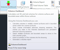
Locate the the Volume Dashboard under Analyze tab.

Locate the panarama, select add volume entry. Add base and comparison surface

Click to generate Cut/Fill Report

Print the report to correct format and insert into the drawing or click the A icon and place report directly into the drawing.
Example of placing the report directly into the drawing.
Locate the the Volume Dashboard under Analyze tab.
Locate the panarama, select add volume entry. Add base and comparison surface

Click to generate Cut/Fill Report

Print the report to correct format and insert into the drawing or click the A icon and place report directly into the drawing.Thursday, May 3, 2012
CIVIL 3D 2013 GOOGLE OUT - BING IS IN
Autodesk has wasted NO time discussing the Google Earth feature missing from Civil 3D 2013. Instead they announced a new plugin from Autodesk Labs that they haved teamed with BING to bring in what looks like dynamic mapping. Video of Bing maps in Civil 3D
Download and install the new feature.
Change the work space to Planning and Analysis
Set drawing coordinate system
Click the Connect icon in the far left of the ribbon.
Now zoom to any location and watch the map update.
Looks very cool so far. Will check accuracy and look for Tin data this weekend.
Download and install the new feature.
Change the work space to Planning and Analysis
Set drawing coordinate system
Click the Connect icon in the far left of the ribbon.
Now zoom to any location and watch the map update.
Looks very cool so far. Will check accuracy and look for Tin data this weekend.
Subscribe to:
Posts (Atom)