Showing posts with label Civil 3D. Show all posts

Wednesday, September 7, 2016

Fired up over Hydrants


Hydrants are a feature people have been wanting since pressure pipes were added to Civil 3D, but have you ever tried to place one in your drawing? Where are the darn hydrants? There is a Hydrant category under the PVC parts list, but you have to manipulate the settings, like all the great functions in C3D, in order to find it. Here’s how we “put out the fire”, and added the Hydrant to our parts list.

Start with setting your ‘Pressure Network Catalog’ to PVC. To do this, from the Home tab, click the drop down next to ‘Create Design’. The tool on the lower left of this pull down will allow you to change what parts catalog you are using. Select PVC.


Return to the Home tab and click on ‘Pipe Network’, select ‘Pressure Network Creation Tools’. When the ‘Create Pressure Pipe Network’ dialog box pops up, under ‘Parts List’, select the drop down next to ‘Edit Current Selection’, and select ‘Create New’.


This prompts the ‘Pressure Network Parts List’ – “New Part List” function to appear.  Name your parts list. If you have ample time you can opt to choose your materials, select what pipes, fittings, and appurtenances you want to use. If not, just simply give the new list a name allowing you to move on to actually locating the elusive Hydrant… 

Right click on your newly created parts list and click on ‘Add type.’  At the bottom of the list is the Hydrant – click on the plus sign to expand the Hydrant category and select the Hydrant by clicking the box to the left. Click ok to save.


Click on the box next to ‘Hydrant_MJ’.
  
Don’t stop here – you still have to select the size of Hydrant. We weren’t joking when we called it elusive.  Expand your “New Parts List” and right click on Hydrant_MJ. Select ‘Add size’ and select the  ‘Add all sizes’ option, as shown below.
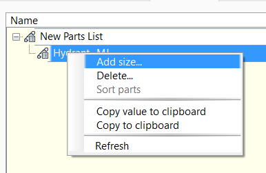


To add a hydrant to your design, draw your pipe network, select the hydrant on the dropdown for appurtenances, and click on ‘Add Appurtenance’. You can now click on your pipe network and add in a hydrant where you need one.


With that, you can now add fire hydrants to your drawing! Check out the video below to see all of the steps described, and others available at ADSK Solutions. For further training and questions, please email info@ADSKsolutions.com.

-Tyler McMillin, E.I.T.


UAV to Civil 3D - GIS Mapping

Just posted to our YouTube channel, 'Adding a GeoTIFF to Civil 3D':

This video shows a GeoTIFF captured by our UAV, and delivered in Civil 3D. We used ReCap 360 to process the data.


-Tyler McMillin, E.I.T.

Thursday, December 13, 2012

Civil 3D Medians and Curb Islands made easy in CORRIDOR

Autodesk University was great again this year. My biggest regret was not meeting with every client that was lucky enough to be out there. I would also like to thank the clients that did hangout. First year that the CRAPS table thanked me for coming to AU.

I spoke for the 4th year in a row and the title of my class was AutoCAD® Civil 3D®: "Curbing" Your Enthusiasm. I presented Conditional corridors for driveways, ADA ramps and sidewalks. I also provide a SOLU-AROUND for medians. Below shows a small portion I presented about medians. I will provide the ultimate part about my class after this solu-around.
This method of creating medians was not practical until the 2012 version. In version 2012 we can add multiple baselines alignments to a single corridor and all assemblies show up together in cross section view. So why not create alignments from each island and use the corridor surface as the profile? This would be dynamic and update as the corridor changes. Unfortunately Civil 3D corridors will not accept the elevation from the corridor profile. Solu-Around, create a new surface called medians. Now paste the corridor surface into it.

·         Create a corridor surface
·         Create a surface called medians
·         Paste the corridor surface into the medians surface
·         Create alignment from the edge of pavement around the median
·         Create profile from median surface.
·         Create assembly using only curb attached to the assembly
·         Add the alignment, profile and assembly to existing corridor
 
I will post part of the AU class or recorded Solu-Around at ADSKSolutions.com I will provide
direct link here.

Friday, October 5, 2012

UNINSTALL REINSTALL Civil 3D 2013

Following directions does not mean everything will work. As a guy that enjoys learning technology I have a habit of just jumping in and clicking buttons, but this time I actually followed Autodesk directions to uninstall Civil 3D 2013 because I didn't have time for this not to work. Unfortunately after following the uninstall document http://usa.autodesk.com/adsk/servlet/ps/dl/item?siteID=123112&id=20304823&linkID=9240697 I was still unable to re-install 2013. During the reinstallation the software thought it was already installed and would not allow me to select the check box for installation. After uninstalling Civil 3D 2013 make sure you locate these registry keys before reinstalling the software.

HKEY_LOCAL_MACHINE\SOFTWARE\Classes\Installer\Products\7D2F3875000B9040112000060BECB6AB

HKEY_LOCAL_MACHINE\SOFTWARE\Classes\Installer\Products\7D2F3875000B9040112000060BECB6AB

After removing these registry keys the software installed properly. Locate the correct keys for Navisworks, Raster Design, ETC before reinstalling the Infrastructure Design Suite.

 *These keys need to be removed for all 2013 products before reinstalling products to ensure success. Match the correct key with the software that was removed.

Thursday, February 2, 2012

Point Cloud Feature Extraction for Revit

Site/Building Footprint Extraction
Autodesk Labs has just released free software to extract Revit data from point clouds. I was reviewing this software to manage, display and extract building data from point clouds. As I was doing this I came across this impressive video on extracting Site/Building Footprints. Autodesk Labs video. To sum this up with one word UNBELIEVABLE!

Remember when Autodesk Labs released Point Cloud Feature Extraction for AutoCAD Civil 3D? (now retired) I would select the point cloud to build a surface and it included all of the trees and utilities. The TIN could not be used for anything.
So I immediately put this new Revit tool to the test. Keep reading I never thought I would use REVIT to build a surface and export it to CIVIL 3D.

Lets get started; Open REVIT and insert the Point Cloud from a simple PTS file.


 Click Feature Extraction from the new TAB and click Site Surface.            
Position the point cloud in the front view like the video displayed and select the ground features.                                                                                                                                                                                               

Image shows resulting point cloud with contours. Notice the wall in the bottom left, and the trees on the site. It automatically excluded these objects. Review the front view below it did not include the trees

 Front view of the surface to show walls and trees were not included.


Couple other helpful tools provide the ability to crop and un-crop the surface. The picture below show the command to turn the point cloud display off.  


 Once the point cloud was turned off I used the Navisworks plug-in to export the surface to Navisworks. 


This command is very simple to use and provides an incredible tool for Revit users to build quick topographical surfaces, but how do we get this surface into Civil 3D?
I will provide steps to utilize this surface in Civil 3D later in the week and will link a video to this process soon.

Thursday, December 29, 2011

Intersection Design with ADA Ramps - Civil 3D

This workflow will utilize conditional subassemblies and automatically place ADA Ramps at selected locations. We will use the Intersection Wizard, draw a couple of polylines, set targets and apply a simple assembly set. The images below represent expected results once code set styles, default settings and custom assembly set have been established.
Download my custom assembly set.(XML File) The image below displays the Sterling Curb Return Fillet assembly that creates the ramps.


1.    Draw at least two alignments; create and design road profiles for intersection design.
3. Start the Intersection Wizard, set parameters. (offset, slopes, radius,etc)

4. Import Custom Assembly set


   5. Complete the wizard

6.    Draw polylines to represent sidewalk ramps.
                                              
7.    This step requires some knowledge of Civil 3D to completely understand the workflow (Solu-Around). Zoom to the assembly set that was imported into the drawing after completing the intersection wizard. Locate the Sterling Curb Return Fillets assembly. This assembly utilizes a conditional subassembly (horizontal targets). Select the intersection; locate edit targets in the ribbon. Select the one corner of the intersection and select target, locate Target Offset (ConditionalHorizontalTarget) select the polyline that represents the ramp. Repeat for the Target Offset below in the same dialog box and select the same polyline.
8. Ramp has been inserted into the corridor. These steps are not a solutions for all intersections or ramps, but a suggestion on how this can be approached. My second Solu-Around will be shown in Part 2. I will show how feature lines are utilized to design ramps. Build a surface from these feature lines and paste the new surface into the corridor surface for final grading.
Watch recorded steps during my 2011 Autodesk University class;

Tuesday, October 18, 2011

Civil 3D 2012 Save As error

Do not use SAVE AS 2007 to save back a Civil 3D 2012 drawing and try to use it in AutoCAD or Land Desktop 2009. The drawing seems to work in 2007, but in 2009 basic editing fuctions are lost. Received erors inserting blocks, copy and paste command.

Had to Wblock the drawing to remove errors. (Recover and audit couldn't repair the problem)

Instead of SAVE AS use Export to AuotoCAD dwg.