Wednesday, September 7, 2016

Fired up over Hydrants


Hydrants are a feature people have been wanting since pressure pipes were added to Civil 3D, but have you ever tried to place one in your drawing? Where are the darn hydrants? There is a Hydrant category under the PVC parts list, but you have to manipulate the settings, like all the great functions in C3D, in order to find it. Here’s how we “put out the fire”, and added the Hydrant to our parts list.

Start with setting your ‘Pressure Network Catalog’ to PVC. To do this, from the Home tab, click the drop down next to ‘Create Design’. The tool on the lower left of this pull down will allow you to change what parts catalog you are using. Select PVC.


Return to the Home tab and click on ‘Pipe Network’, select ‘Pressure Network Creation Tools’. When the ‘Create Pressure Pipe Network’ dialog box pops up, under ‘Parts List’, select the drop down next to ‘Edit Current Selection’, and select ‘Create New’.


This prompts the ‘Pressure Network Parts List’ – “New Part List” function to appear.  Name your parts list. If you have ample time you can opt to choose your materials, select what pipes, fittings, and appurtenances you want to use. If not, just simply give the new list a name allowing you to move on to actually locating the elusive Hydrant… 

Right click on your newly created parts list and click on ‘Add type.’  At the bottom of the list is the Hydrant – click on the plus sign to expand the Hydrant category and select the Hydrant by clicking the box to the left. Click ok to save.


Click on the box next to ‘Hydrant_MJ’.
  
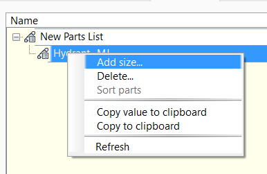
Don’t stop here – you still have to select the size of Hydrant. We weren’t joking when we called it elusive.  Expand your “New Parts List” and right click on Hydrant_MJ. Select ‘Add size’ and select the  ‘Add all sizes’ option, as shown below.


To add a hydrant to your design, draw your pipe network, select the hydrant on the dropdown for appurtenances, and click on ‘Add Appurtenance’. You can now click on your pipe network and add in a hydrant where you need one.


With that, you can now add fire hydrants to your drawing! Check out the video below to see all of the steps described, and others available at ADSK Solutions. For further training and questions, please email info@ADSKsolutions.com.

-Tyler McMillin, E.I.T.


UAV to Civil 3D - GIS Mapping

Just posted to our YouTube channel, 'Adding a GeoTIFF to Civil 3D':

This video shows a GeoTIFF captured by our UAV, and delivered in Civil 3D. We used ReCap 360 to process the data.


-Tyler McMillin, E.I.T.
Monday, August 11, 2014

Civil 3D 2015 service pack 1


#1  Issue that has been resolved where material take off would compute only half of the areas of the materials when more than one baseline existed. Download sp1

Corridor Modeling and Analysis
  • A data-specific issue has been resolved where attempting to rebuild a corridor would cause the application to close unexpectedly.
  • An issue has been resolved where material take off would compute only half of the areas of the materials when more than one baseline existed.
  • An issue has been resolved where the corridor feature line areas were not using the code set styles assigned to the corridor.
  • An issue has been resolved where the elevation target in the DaylightBasin and DaylightBasin 2 subassemblies was incorrectly solving for the basin elevation.
  • An issue has been resolved where the German Country Kit assembly GermanSA_Fahrbahn_ausserorts was missing the feature line on the right side in a cut terrain situation.
Pipe Networks and Pressure Networks
  • An issue has been resolved where data-referenced gravity pipe network styles were reset when the source model was updated and the network was synchronized.
  • An issue has been resolved where data-referenced pressure network styles were reset when the source model was updated and the network was synchronized.
  • An issue has been resolved where pressure networks were not created properly when using the Create Pressure Network from Industry Model command.
  • An issue has been resolved where an invalid part and/or pipe style within a pipe network would cause the application to close unexpectedly.
Alignments and Profiles
  • An issue has been resolved where editing an alignment when another profile had been superimposed onto its profile would cause the application to close unexpectedly.
  • An issue has been resolved regarding the adjustment of the profile station range when creating a profile after creating and deleting an unrelated alignment.
Survey
  • A utility which provides the ability to save an AutoCAD Civil 3D 2015 survey database for use in AutoCAD Civil 3D 2014 is included in this service pack. This utility can be accessed from the AutoCAD Civil 3D Toolbox after installing this service pack.
  • An issue has been resolved where attempting to delete a survey figure from the Figures Editor would cause the application to close unexpectedly.
Grading and Surfaces
  • An issue has been resolved where deleting all grading projections and repeatedly running the UNDO command would cause the application to close unexpectedly.
  • An issue has been resolved where deleting points from a surface when the DACH Extension is installed would cause the application to close unexpectedly.
  • An issue has been resolved where draped images that were rendered when hardware acceleration was turned on would be mirrored.
Miscellaneous
  • An issue has been resolved where a description was not included from a data-referenced source object.
  • An issue has been resolved where unexpected characters and text was added to objects in a drawing and within any drawings that were opened during the AutoCAD Civil 3D session.
  • An issue has been resolved where starting AutoCAD Civil 3D in zero document state startup mode would cause the application to close unexpectedly.
  • An issue has been resolved where the correct CODES file was not being read from the registry.
  • An issue has been resolved where modifying an object on a locked layer would cause the application to close unexpectedly.
  • An issue has been resolved where a curve label would show its content reversed when located at 0 and 180 degrees in a drawing.
  • An issue has been resolved where the Print button in the Hydraflow Express Rainfall IDF Curve dialog box would not work properly.


Saturday, June 29, 2013

Civil 3D 2014 Update

I was working in Civil 3D again today. Yes it is Saturday and I was trying to get some work done when Autodesk provided me a balloon notification to update my Civil 3D 2014 software because it was out of date. I clicked the click and it brought up the image below. Selected update, read the readme. Yes I did do it and software is up to date. The readme displayed many reasons to install the hotfix. Most solutions were to enhance stability.


While I waited for the install to complete I searched for other important updates and solutions.

GIS professionals = MAPIMPORT or MAPEXPORT doesn't work
Point Cloud professionals = AutoCAD Reality Capture Memory Leak Hotfix
 Review most recent updates and solutionsCivil 3D Updates & Service PacksTroubleshooting

Tuesday, April 23, 2013

State plane versus Aussumed coordinates

It has become more and more common to capture information with state plan coordinates. Unfortunatley data still is required with assumed coordintates. Client demands and request provide reality capture firms delivering data state planes and assumed coordinates. AutoCAD Civil 3D will deliver both if styles and settings are set up properly. I have provided an image below and images to compare your existing workflow and data with ADSK Solutions Solu-arounds.

As posted above; create a new style and select segment direction and select grid direction. Place this under segment direction to copy the style attached. Both coordinates will match. It is recommended to create multiply lable styles to display pertinant information. To display state plane and assumed coordinates users can select the settings tab from the prospector and right click drawing settings. In the transformation settings specify grid and rotation angle. This will display the assumed coordinates. Contact info@ADSKsolutions.com to understand Stae plan and assumed coordinates.

Thanks,
Chad Studer
248-894-5209

Wednesday, April 3, 2013

Download Civil 3D 2014 now

http://www.autodesk.com/products/autodesk-autocad-civil-3d/free-trial

First thing I recommend is downloading Autodesk ReCap Studio and inserting point clouds. They did a great job with the new point cloud engine.

I will provide a dataset upon request.

ChadStuder@ADSKsolutions.com

Wednesday, March 27, 2013

Autodesk ReCap Point Cloud Software for download

Create intelligent 3D data from photos and scans
Autodesk® ReCap delivers powerful and easy to use workflow on the desktop and in the cloud to create intelligent 3D models from laser scans and captured photos. Rather than beginning with a blank sheet, Autodesk ReCap now enables any designer, architect or engineer to add, modify, validate and document their design process in context from existing environments.


Download Autodesk RECAP
  • Autodesk ReCap Studio - Seamlessly integrated with Autodesk Design and Creation suites, Autodesk ReCap Studio makes it easy to clean, organize, and visualize massive datasets captured from reality.
    Download Autodesk ReCap Studio for free
  • Autodesk ReCap Photo - Autodesk ReCap Photo helps users create high-resolution textured 3D models from photos using the power of cloud computing. Autodesk ReCap Photo will be available April 12, 2013

    View Autodesk ReCap Demo Video

  • Contact ADSK Solutions for professional trainig and innovative solutions for design. 248-906-2375

    More information: http://thenextweb.com/insider/2013/03/26/autodesk-announces-recap-new-3d-scanning-apps-targeting-designers-and-engineers/

    Tuesday, December 18, 2012

    PTS to LAS POINTCLOUDS in CIVIL 3D

    I have been working with Leica HDS Laser Scanners since 1999. My company is a Leica HDS GOLD dealer and we specialize in implementing scanning and creating deliverables utilizing Leica HDS and Autodesk software. Over the past few years the typical solution(easy) is to work with PTS file format and it does provide a solution, but we can also convert the PTS format to LAS or E57 format. We are located in Michigan and MDOT requires a LAS in their RFP.

    We recommend exporting Leica HDS IMP data in pts format and converting it to a LAS file for importing into Civil 3D or REVIT. This will reduce the file sixe by almost 75%. To convert the PTS to LAS we can utilize a very simple and free software called POINTZIP. Yes this is free software and yes the icon is a DUCK. I was afraid to download this free software with the .exe extension and the picture of a duck., but now after testing this product I give my stamp of approval. now.

    Download while it is FREE


    During the conversion process color can be retained if you select the xyzRGB option below.


    Once Civil 3D is open, simply right click Pointclouds from the Prospector and Create Point Cloud. From Revit, select insert POINTCLOUD, select the las file and convert to PCG.
     
     
    Select Truecolor to display Pointcloud color from the images that were taken. Below is an image of what to expect once the pointcloud is imported.
     We plan to elaberate on our next post about the advantages and disadvantages of points directly imported into Civil 3D or any Autodesk format. We will also provide solutions for importing pointclounds into Revit, Navisworks, and Factory CAD. We will also provide solutions and workflows for working with the new E57. E57 file format is a compact, vendor-neutral format for storing point clouds, images, and metadata produced by 3D imaging systems, such as laser scanners.
     
    Happy Holidays to all!
    Chad Studer


    Monday, December 17, 2012

    Civil 3D APPS ON DEMAND

    ALL I want for Christmas is a Civil 3D APP. I have been looking at these and wanting to test them forever. Now that Autodesk University is behind us it's time to start playing again. Please post if you have downloaded any APPS and feel free to review them here. I will begin my reviews the first of the year.  http://apps.exchange.autodesk.com/CIV3D/Home/Index


     My favorite so far is the E57 file format for pointclouds. I will discuss this more on my next post along with the LAS file format for pointclouds in Civil 3D.


    E57 file format plug-in for Pointclouds in Civil 3D 2013


    The next review will be makinga copy 3D polylines/Featurelines and placing them in 2D.


    Thursday, December 13, 2012

    Civil 3D Medians and Curb Islands made easy in CORRIDOR

    Autodesk University was great again this year. My biggest regret was not meeting with every client that was lucky enough to be out there. I would also like to thank the clients that did hangout. First year that the CRAPS table thanked me for coming to AU.

    I spoke for the 4th year in a row and the title of my class was AutoCAD® Civil 3D®: "Curbing" Your Enthusiasm. I presented Conditional corridors for driveways, ADA ramps and sidewalks. I also provide a SOLU-AROUND for medians. Below shows a small portion I presented about medians. I will provide the ultimate part about my class after this solu-around.
    This method of creating medians was not practical until the 2012 version. In version 2012 we can add multiple baselines alignments to a single corridor and all assemblies show up together in cross section view. So why not create alignments from each island and use the corridor surface as the profile? This would be dynamic and update as the corridor changes. Unfortunately Civil 3D corridors will not accept the elevation from the corridor profile. Solu-Around, create a new surface called medians. Now paste the corridor surface into it.

    ·         Create a corridor surface
    ·         Create a surface called medians
    ·         Paste the corridor surface into the medians surface
    ·         Create alignment from the edge of pavement around the median
    ·         Create profile from median surface.
    ·         Create assembly using only curb attached to the assembly
    ·         Add the alignment, profile and assembly to existing corridor
     
    I will post part of the AU class or recorded Solu-Around at ADSKSolutions.com I will provide
    direct link here.

    Friday, October 5, 2012

    UNINSTALL REINSTALL Civil 3D 2013

    Following directions does not mean everything will work. As a guy that enjoys learning technology I have a habit of just jumping in and clicking buttons, but this time I actually followed Autodesk directions to uninstall Civil 3D 2013 because I didn't have time for this not to work. Unfortunately after following the uninstall document http://usa.autodesk.com/adsk/servlet/ps/dl/item?siteID=123112&id=20304823&linkID=9240697 I was still unable to re-install 2013. During the reinstallation the software thought it was already installed and would not allow me to select the check box for installation. After uninstalling Civil 3D 2013 make sure you locate these registry keys before reinstalling the software.

    HKEY_LOCAL_MACHINE\SOFTWARE\Classes\Installer\Products\7D2F3875000B9040112000060BECB6AB

    HKEY_LOCAL_MACHINE\SOFTWARE\Classes\Installer\Products\7D2F3875000B9040112000060BECB6AB

    After removing these registry keys the software installed properly. Locate the correct keys for Navisworks, Raster Design, ETC before reinstalling the Infrastructure Design Suite.

     *These keys need to be removed for all 2013 products before reinstalling products to ensure success. Match the correct key with the software that was removed.

    Tuesday, September 18, 2012

    REVIT LT for SCAN to BIM Professionals

    As a Civil 3D and SCAN to BIM professional it is important to understand Revit. Autodesk has just released Revit LT. This provides a low cost platform for everyone to own a BIM Solutions and yes this LT version includes 3D, LOL. The full version of Revit is required for rendering materials.

    Revit LT can be purchased as a stand-alone product.
    Free Trial - http://usa.autodesk.com/revitlt/trial/
    Features - http://usa.autodesk.com/revitlt/features/
    How to buy - http://usa.autodesk.com/revitlt/howtobuy/


    Saturday, August 18, 2012

    Volume Reports and Tables in Civil 3D 2013

    Civil 3D will create CUT & FILL Reports and Tables utilizing the Dashboard in Civil 3D 2013 or the extension in 2012.

    Locate the the Volume Dashboard under Analyze tab.


    Locate the panarama, select add volume entry. Add base and comparison surface


    Click to generate Cut/Fill Report


    Print the report to correct format and insert into the drawing or click the A icon and place report directly into the drawing.


    Example of placing the report directly into the drawing.

    Thursday, May 3, 2012

    CIVIL 3D 2013 GOOGLE OUT - BING IS IN

    Autodesk has wasted NO time discussing the Google Earth feature missing from Civil 3D 2013. Instead they announced a new plugin from Autodesk Labs that they haved teamed with BING to bring in what looks like dynamic mapping. Video of Bing maps in Civil 3D

    Download and install the new feature.
    Change the work space to Planning and Analysis
    Set drawing coordinate system
    Click the Connect icon in the far left of the ribbon.


    Now zoom to any location and watch the map update.
    Looks very cool so far. Will check accuracy and look for Tin data this weekend.

    Friday, April 6, 2012

    Download Civil 3D 2013 and read system requirments

    Civil 3D 2013 and Infrastructure suites have been released.

    If you haven't received your 2013 product it is posted online. You can download and run the software for 30 days or until your product serial number arrives. If you are on subscription download load it from the subscription center. Check out new features, requirments and more below. Please call if you are interested in 2013 training. We are also offering local and webinar rollout events. 480-719-4599
    Autodesk 2013 live and webinar events
    Civil 3D 2013 Download
    2013 Infrastructure Design Suite Download
    Autodesk Subscription
    Civil 3D 2013 Requirements
    Civil 3D 2013 Features
    Infrastructure Design Suite and Civil 3D information INFO

    Wednesday, March 28, 2012

    Civil 3D 2013

    Before we talk about the new version let's go OLD SCHOOL. Anybody remember AutoCAD R13? Was R13 that bad or was R14 that good? I wish Autodesk would of released and titled the new release Civil 3D NV (New Version) for all of us old school R13 was the version we could of all did with out. Maybe Autodesk could have gone with Civil 3D PRE-2014. The good news is they redeemed themselves with this R13 release. Attached provides a list of all of the new features. Can you say water main without getting excited?
     Civil 3D 2013 Matrix

    I plan to introduce and break down each feature for you after we present our local live events on 2013 Autodesk products. www.ADSKsolutions.com

    Thursday, February 2, 2012

    Point Cloud Feature Extraction for Revit

    Site/Building Footprint Extraction
    Autodesk Labs has just released free software to extract Revit data from point clouds. I was reviewing this software to manage, display and extract building data from point clouds. As I was doing this I came across this impressive video on extracting Site/Building Footprints. Autodesk Labs video. To sum this up with one word UNBELIEVABLE!

    Remember when Autodesk Labs released Point Cloud Feature Extraction for AutoCAD Civil 3D? (now retired) I would select the point cloud to build a surface and it included all of the trees and utilities. The TIN could not be used for anything.
    So I immediately put this new Revit tool to the test. Keep reading I never thought I would use REVIT to build a surface and export it to CIVIL 3D.

    Lets get started; Open REVIT and insert the Point Cloud from a simple PTS file.


     Click Feature Extraction from the new TAB and click Site Surface.            
    Position the point cloud in the front view like the video displayed and select the ground features.                                                                                                                                                                                               

    Image shows resulting point cloud with contours. Notice the wall in the bottom left, and the trees on the site. It automatically excluded these objects. Review the front view below it did not include the trees

     Front view of the surface to show walls and trees were not included.


    Couple other helpful tools provide the ability to crop and un-crop the surface. The picture below show the command to turn the point cloud display off.  


     Once the point cloud was turned off I used the Navisworks plug-in to export the surface to Navisworks. 


    This command is very simple to use and provides an incredible tool for Revit users to build quick topographical surfaces, but how do we get this surface into Civil 3D?
    I will provide steps to utilize this surface in Civil 3D later in the week and will link a video to this process soon.

    Tuesday, January 24, 2012

    Autodesk Live Event, Scottsdale, AZ

    Chad Studer presents Civil 3D break-out session with Lynn Allen"The Future of Design" seminar with Lynn Allen on Thursday, February 16th in Old Town Scottsdale, AZ. No Registration Fees.
    Lynn is the most sought after Autodesk Technical speaker and speaks to 30,000 uses each year.
    Register for more details
    Live Event in Old Town Scottsdale: No Registration Fees


    • Future of Design
    • Civil 3D Break-out
    • Revit Break-out Session      
    • 60 Tips in 60 Minutes
    • Networking Happy Hour!
    !


    Thursday, December 29, 2011

    Intersection Design with ADA Ramps - Civil 3D

    This workflow will utilize conditional subassemblies and automatically place ADA Ramps at selected locations. We will use the Intersection Wizard, draw a couple of polylines, set targets and apply a simple assembly set. The images below represent expected results once code set styles, default settings and custom assembly set have been established.
    Download my custom assembly set.(XML File) The image below displays the Sterling Curb Return Fillet assembly that creates the ramps.


    1.    Draw at least two alignments; create and design road profiles for intersection design.
    3. Start the Intersection Wizard, set parameters. (offset, slopes, radius,etc)

    4. Import Custom Assembly set


       5. Complete the wizard

    6.    Draw polylines to represent sidewalk ramps.
                                                  
    7.    This step requires some knowledge of Civil 3D to completely understand the workflow (Solu-Around). Zoom to the assembly set that was imported into the drawing after completing the intersection wizard. Locate the Sterling Curb Return Fillets assembly. This assembly utilizes a conditional subassembly (horizontal targets). Select the intersection; locate edit targets in the ribbon. Select the one corner of the intersection and select target, locate Target Offset (ConditionalHorizontalTarget) select the polyline that represents the ramp. Repeat for the Target Offset below in the same dialog box and select the same polyline.
    8. Ramp has been inserted into the corridor. These steps are not a solutions for all intersections or ramps, but a suggestion on how this can be approached. My second Solu-Around will be shown in Part 2. I will show how feature lines are utilized to design ramps. Build a surface from these feature lines and paste the new surface into the corridor surface for final grading.
    Watch recorded steps during my 2011 Autodesk University class;

    Monday, December 12, 2011

    Vertical road alignments designed by the CLOUD

    Wow! What is coming next? I uploaded the existing ground profile to the Cloud and it came back with the the road completly designed and a report was included. If I send a dollar to the CLOUD I wonder if it would send $100 back?

    Ok, the truth is, it does send back a vertical alignment and it is optimized to meet minimum, maximum grade and pvi matching can be set.

    Install the software from Autodesk Labs. Project Silverstar for AutoCAD Civil 3D This software will be located in the Toolspace under the Toolbox. Profile Optimization. Login to subscription and create a login into the Autodesk Cloud.


    Right click to start this new utility. Login to the Autodesk Cloud (Existing ground profile is required) **Make sure a design speed is provided.


    Set minimum and maximum grades, toggle matching PVI's.


    Set PVI intensity, and notice
    Maximum Solving Time.


    BAM! The Cloud has received the data. All we have to do is wait for the return email. I planned on posting the results so I set the maximum time to 1 minute. Unfortunately it has been 1/2 hour and I have not received an email. Going to bed and will post the results tomorrow.

    The results were returned from the cloud in about 1.5 hours. I have posted the Report, XML, and the ASCII file on the Autodesk CLOUD. Did you expect anything else? It only takes a second to view or download.
    PDF report - https://documents.cloud.autodesk.com/Public/Details?hash=tYUTSWt
    XML file - https://documents.cloud.autodesk.com/Public/Details?hash=tYUTdbM
    ASCII file - https://documents.cloud.autodesk.com/Public/Details?hash=tYUTNX2

    I believe this utility has a lot of potential. I would like it to ask for all PVI elevations that I have to match. Main roads, secondary roads etc. This utility is very similar to the best fit profile utility with a couple more options. Given the time it takes to return the design I believe this is more of a introduction to the Cloud then a program I can utilize at this time. Below are the steps to create a Best Fit Design Profile.
    *See image below for best fit profile utility.

    The team at Autodesk Labs is very responsive to all feedback. I cannot encourage you enough to share your expectations or obstacles. Below is the feedback that was returned to me.

    Dear Mr. Studer,


    Thank you for the valuable feedback. If you do not mind, I would be happy to discuss Project Silverstar further with you, in order to get more feedback?

    First about the delay. I quickly looked at the log files on the cloud. Unfortunately, your job with the short solving time was just queued up behind some longer jobs. This is why you didn’t receive an answer quickly. We are working on improving our load-balancing to avoid such situations in the future as best as possible.

    (I suggested the ability to add more PVI's)
    Adding more PVI is a feature that we actually thought about already. I don’t think it would be a major problem to add this on the cloud side. On the client side (wizard), how would you, from a user perspective, best like to enter the PVI information? Would a list similar to the one for borrow/waste pits be a solution? One problem with such a list is that a user could potentially enter PVI’s that will conflict with other design constraints (minimum tangent length, grade constraints, etc.). Designing a user interface that takes that into account without confusing the user would be nice, but can be tricky. If you have any ideas or suggestions in this respect, please let me know.

    As for the similarities with the best fit utility, SilverStar works actually quite different. The Best Fit utility tries to find a profile that fits the ground as close as possible. This can be computed very fast. SilverStar, on the other hand, tries to find a profile that minimizes total earthwork costs (cut, fill, load, and especially hauling), subject to a set of design constraints. From a computational perspective, this is a hard problem which requires significantly more computation time than Best Fit. This is one of the reason that the SilverStar algorithm is in the Cloud.

    I hope this explains some of the issues. I am looking forward to get more feedback from you in order to get SilverStar more usable.

    Thank you very much,
    Valentin Koch
    Principal Research Engineer
    AEC IM
    Autodesk Inc.