Tuesday, August 31, 2010

Profile creation from a Feature Line

Select a feature line, right click and create a quick profile. A quick profile can be saved by exporting an xml file before saving the drawing. Importing the xml file will create an alignment. Use the create profile command to re-display the quick profile. Below are a few examples where this could be used.

Create a profile from a single row of points.
Draw a feature line using the transparent command point objects (‘PO). Connect the row of points. Select the feature line, right click and create a quick profile. Export and then import the xml file. Using the profile pulldown select create profile view.

Design a parking lot with feature lines - Daylighting
Design a parking lot with feature lines. Select the feature line, right click and create a quick profile. Export and then import the xml file. Create a profile view, now you can use an assembly to daylight the parking lot.
Drainage review – Parking Lot, Drains, ETC
This could also be used to analyze edge of pavement or curb lines for drainage. Create a quick profile from any feature line. Choose different styles to display existing ground and the feature line as the finished ground. Under the home tab locate Profile View, select the last option, Project Objects To Profile View. (This requires style to display labels and symbols.)

*NOTE: The profile is only temporary unless it is exported as xml and re-imported. (See steps above)


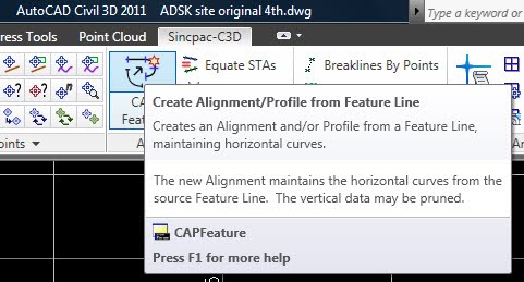
I pulled this Solu-Around from the bottom of my Civil 3D TIP JAR. If you have been utilizing this feature and understand its potential like I have, check out the upgraded version at Sincpac-C3D. http://www.quuxsoft.com/


It has been brought to my attention, that the alignment is not created after importing the XML in Civil 3D 2011. Like I said this tip was pulled from the tip jar. The Solu-Around (solution) is to click pick from drawing and select the profile to export. Now when you import the XML the alignment will be there.


Tuesday, August 17, 2010

Does the BIGGEST mean the BEST?

Two of the largest Autodesk resellers become one!

RAND WORLDWIDE, INC. AND AVATECH SOLUTIONS, INC.
This will form the larget Autodesk global VAR
http://www.rand.com/1/about/investor/news2010.htm

Wednesday, August 4, 2010

Essential grade label for Site Design

Arrows reflect grade; elevation and grades update as modified.


Styles are imperative to Civil 3D and I haven’t even mentioned my favorites in this blog yet. The first one I would like to introduce is an oldie, but it always slips under the radar. I’m sure by now everyone is familiar with direction arrows for line labels, but did you know that out of the box Civil 3D provides a direction label style for grades? Apply this to any feature line and it places an arrow pointing in the downhill direction. To try this open the NSC template and click on the Annotate tab, click add labels and select Grade only for the label styles.

The secret is an expression that was created to allow the direction arrow to rotate.

The default label style should look like this after placing labels on a feature line with elevations.
Detailed information from Autodesk


Now that we have found the default style let’s elaborate by adding elevations.Copy the current style and rename it ELEV & Grades. Add a text component.


Configure Anchor Point to the Start of each feature line, add the elevation to the start segment, rotate it 90 and set an offset.

The new style should include elevations. Make sure you repeat for curve labels.


Now it’s time to have some fun with this style by adding markers and moving the arrows to the lines.


Modify the design and watch the elevations, grades and slope arrows automatically update. Add Sincpac (3rd party software and link the points to the feature lines.)Please look for future post as we discuss this style, and other solu-arounds for site grading.

Shoot me an email and I will send the completed style to you. Should be posted on ADSK Solutions website soon.